I was hoping to write the second part of the servo motor control part sooner... But you know how life and 2020, in general, have been. I don't really have anything new to say about the state of the world. It's still terrible, and only getting worse.
Anyhow. Let's start with the servo stuff. In the last post, I tried to explain what a general servo is, and how the sermovotor I have differed from the ones you can buy from general hobby electronics shop. TLDR
- Continous rotation
- High speed (up to 7000 RPM)
- Precise control - 0.1 Degrees accurate in rotation
- Inbuild microcontroller with Digital and Analog I/O
- Inbuilt temperature sensor based protection systes for overheating
- Daisy chaining with each motor having its own program stored inside
So basically its in a different league. Which is cool and all, but how do you ultimately use something like this?
Keep in mind this post and the previous one infact are specific to the Faulhaber motor I have. I would like to believe that similar speced servomotor from other manufacturers would also be similar, to make life easier for people. But I cannot guarantee that. Thankfully, certain things like CANBus and RS485 are infact standards of communications. How well they are implemented and how user friendly the parent company makes them to the end user, is a different story.
Let's start with the list of things you need. Again, probably highly specific to my particular motor, but use the datasheets to find out what you need.
- The motor - I have the Faulhaber CSD-BX4 xxxxx family
- The Control board - Something that links your motor to the PC for testing and programming
I have the Programming adapter for Motion control v2.5 with Mini USB port. - A power supply - Ideally on the nominal voltage of your specific motor, but any voltage range in the datasheet will work (Usually 8-30V). Obviously if you are not using the nominal voltage, you will not get the nominal performance. I used a 12 VDC wall adapter on a 24V nominal motor. (boo)
Let's start with the wiring and config of the USB controller board.
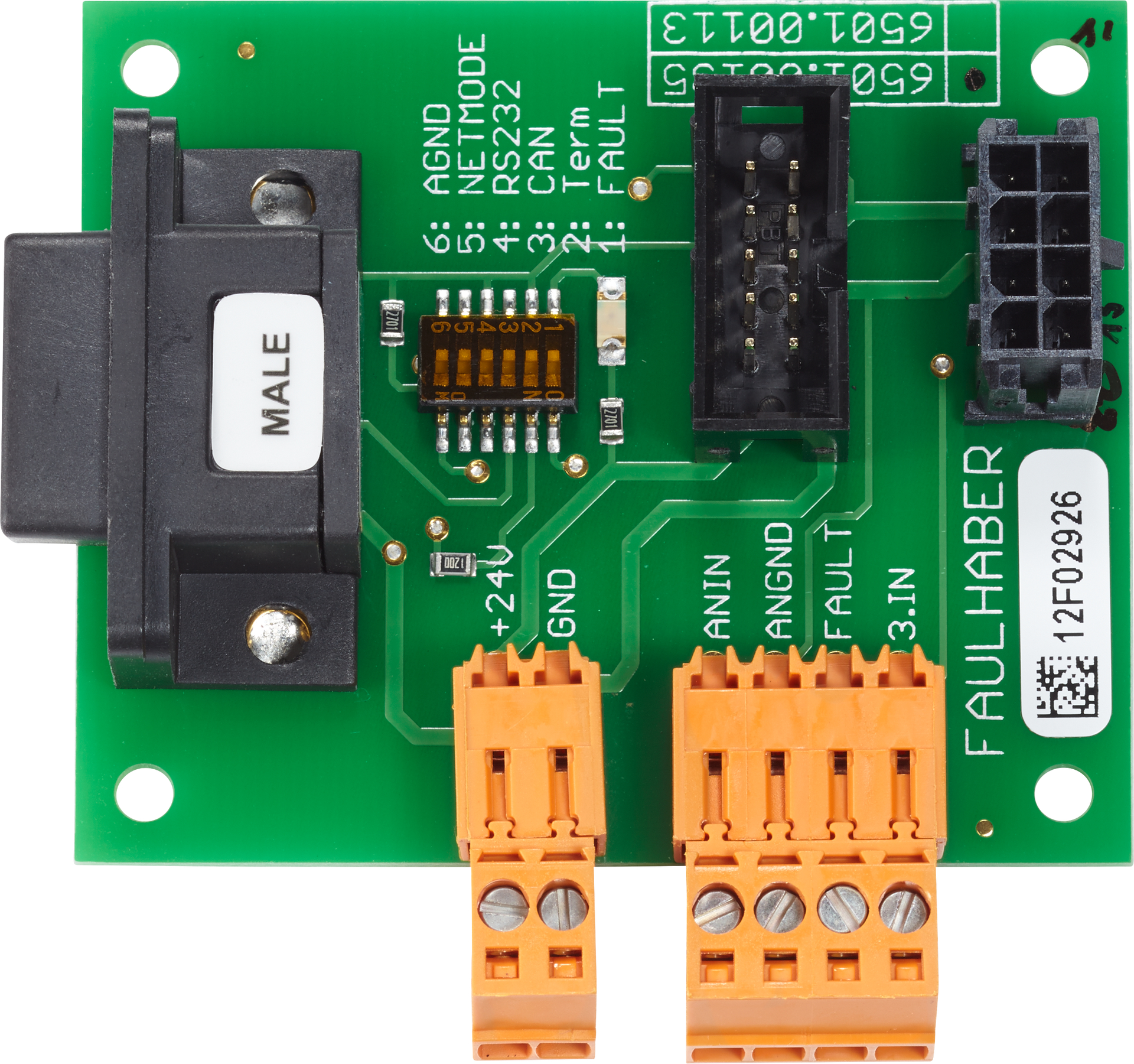
- In the small orange screw terminal / jack - you have your power input and ground. +24 is the Positive and GND is... Ground.
- The 4 pin screw jack is the I/O and other interfaces that are used with the motor. We're not playing with that today.
- 6 DIP switches - They are quite important as they configure the I/O fault connections and overall interface in the motor. Look in the datasheet of your own control/interface board to set it up properly. For my case, I have kept 1 and 4 to high. This corresponts to a connected FAULT LED on the board the programming interface mode to USB.
- Finally both the 2x5 pin block and the PCIe looking connector are the motor connectors. You can attach 2 motors to a single board in this case.
Once you have connected and set it up properly. Just connect the board to the computer which already has the Faulhaber motion control software installed.
Keep in mind that the board is not powered by the USB, and you will need the 12/24V going into the board from an external source for the PC to detect the motor.
Once connected, you should hear the windows notification sound for a connected device.
The software should automatically promt you to set up your motor. If not, look on the right edge of the window, and find "Establish connection" option.

Identify the COM port over which the motor is connected. Usually it would only be a single COM port, with proper labelling anyway.

Choose the controller version. This depends on the motor and the control board. We have the V 2.5 so select V2.x


Click Search. The software should detect the motor model that is connected.


Here you would need to enter the exact model of the motor you have. Including the variation of positional sensors being employed in your motor. Finally, you need to change for the correct input voltage. E.g - I should change it to 12.2V based on what my multimeter shows.

Once you are happy with the data, hit next.

Faulhaber sells gearboxes meant to be attached directly to the shaft of the servo as well. In case you are using a gearhead or any other systems, add the relevant data to the application here. Since I am just fooling around, I do not have anything at the motor shaft. You can also limit the max speed of the motor here, if you so desire. Again, keep in mind that if you set a speed that is too high for the given supply voltage, it is pointless. Also, If the speed is kept slow, in Velocity control mode, the motor will draw more currect just so that it can maintain the required RPM. More on that later.

This is probably the coolest step. Because you will have some rotational mass on your motor in practical use, it will have a certain moment of inertia. Hence, the motor would need to compensate its behaviour based on the mass and the geometry of the load on the motor. Once you know the J of the load, simply add the value here and the software will calculate the resultant J for the overall system.
Protip - I am a bad mechnanical engineer and I do not know how to compute J for objects. So I made a simple quick model of what I was supposed to attached on the shaft in Fusion 360 and simply noted the Ixx value it showed me. After selecting the correct material, ofcourse. I am not that bad.

This is more fine tuning of the control behaviour of the motor, and how you want the motor to achive it's desired state. Hit Next.

BOOM! Based on the J value and the control preference you decided, the software calculates the PID values of the build in controller just like that! Obviously it might not be what you need, or it may need fine tuning... But you can change them manually later anyways! I just thought this is very cool!
With this, we are also at the end of the inital motor setup.
Now, in the tools section, look for Motion cockpit as well as the Graphic analysis part. Open and arrange the respective windows how you deem suitable. It is now time to run the servo.

This is the motion control window. Here you can set the mode of operation for the motor. We have 3 options here -
- Position - Motor counts the number of revolutions are rotates by a certain amout, at the max possible velocity. Both absolute and relative position control are possible.
- Velocity - Motor spins - or tries to spin at the set RPM. Both clockwise and counterclockwise. Velocity is dependent on the voltage supplied - keep that in mind.
- Voltage - supplies a certain voltage to the motor - Useful for torque control. You can apply both +ve and -ve voltage from the software itself to change the direction of rotation.

You can also use the setpoint function to alternate between the 2 defined states after a certain interval. Note that these are just for the testing purpose and not the actual programming of the motor.

This is what the actual programming interface of the Faulhaber software looks like. I have arranged the windows to match my taste. The left side is the programming side, with some example code to get started. It is based on BASIC language with some faulhaber specific modification from what I can tell.
I have not spent too much time on it, but it looks to be "not so hard".

Here, I am running the motor in position control mode, alternating it between +9000 and -3000 steps from zero. The motor rotates at full speed for both directions. Notice the huge current spikes when the motor is changing direcition? Smaller spike is when it slows down to 0 RPM, the bigger spike is when it tries to accelerate back again. Keep an eye on the time scale at the bottom as well. It goes from approx -3000RPM to 3000RPM in less than half a second.

Here you see the velocity control mode in action. Notice how the motor tries to maintain the -1100 RPM at the shaft but the current is varying quite a lot? That's because the current spikes correspond actively to the load/braking force I was applying on the shaft with my fingers. The motor detects the load on the shaft due to it slowing down, and then tries to compensate the slowdown by increasing the torque and thus the current to the coils in the motor. I managed to draw a peak of just over 350 mA before the powersupply I was using hit it's limit. The motor *has* an inbuild current protection device, but it is generally a good idea to not use a power supply capable of much more current than what your device would actually need. For example, running this motor on a lead acid battery or a ATX PSU capable of 50+ Amps is just plain stupid.
Interestingly this is also something that is very commonly used for collision detection in industrial robots. When you program the robot, the software calculates the motion the robot will take. That motion is then computed over to estimate the current that would be required by the motors to move the robot for position A to position B with the required velocity. When the robot is in motion, the current drawn is compared to the predicted current draw of the robot at that particular position. If the current draw exceeds the precomputed value by a certain margin, the robot can assume there is a collision or an obstruction in the robot path and stop the motion of the robot.
As you can probably image, this is quite complex, both in theory and computationally. Not only you need to know about the characteristics of the motor and drive system, you need to know about the weight of the robot and it's payloads, and compute and compare the current values of the motor multiple times - usually 100 per second, all while actaully moving the robot.
As you can probably image, this is quite complex, both in theory and computationally. Not only you need to know about the characteristics of the motor and drive system, you need to know about the weight of the robot and it's payloads, and compute and compare the current values of the motor multiple times - usually 100 per second, all while actaully moving the robot.
Obviously this method is not as good as using a dedicated force torque sensor in the robot, but you get basically free collision detection with just additional computation without any additional hardware.

- Start at 100 RPM - and at 2000 RPM
- After a delay of 100 ms execute the following loop
- Request velocity
- Store requested velocity in variable B
- Add 100 RPM to variable B
- Set the new B as the velocity
- Wait 100ms for new velocity to take effect
- As long as the velocity after loop is less than 2000, jump back to loop.
Basically the motor starts at 100 RPM and gains speed by 100 after every 1 second. You can see that from the graph as well.
Obviosly this is a very simple program and you can make much more complex ones. But that's it for now. It's all a matter of time and patience, neither of which I have right now.
Which is also the reason I'll end this post without any photos or music recommendations. Hopefully, I will have some for the next post. What it will be about and when it will be, *shruggie*
I hope this proves useful to someone somewhere sometime. Thank you for your time, and have a nice day. 😊
Comments
Post a Comment